
B.I.O.G.A.T.O.R.
May 2020 - Aug. 2020

Project Description
For this semester’s Capstone Design project, all groups were tasked with designing a 3D bioprinter that could mount onto the turret fixture of a Nikon Eclipse Ti confocal microscope. The purpose of this bioprinter was to fulfill a need within the UF Soft Matter Engineering Group to create a device that could print live cells into a liquid-like solid to create high-resolution biostructures, which would be visualized via confocal microscopy. The intent was to design a repeatable, reliable, and robust bioprinter with potential to be mass produced for sale to commercial and industrial laboratories. A representative from the Soft Matter Group presented our class with a Customer Requirements list to guide our designs, which can be seen below.
General Requirements
1. Mountable: Printer must be mounted to the condenser turret of a Nikon Eclipse Ti confocal microscope
2. Size: Primary structure must fit within a 100 mm cube
3. Weight: 200 g max
4. Linear accuracy: < 1 cell diameter
5. Linear speed: Min ~ 1 μm/s, slower is better; cannot cause LLS instabilities at high speed.
6. Maximum print extents: Must be able to print through the full volume of a single well of a standard biological 96 well plate. Z-travel should be equivalent to X/Y max.
7. Motion must be transmitted to printer stages from a remote source. Motors are not allowed to be mounted directly on 3D Bio-Printer stages; must be at least 2 feet away from microscope centerline. This means that no motors are allowed to be connected to or within the 100 mm cube defined above. No piezoelectric actuators can be used as they are not controllable with a Smoothieboard 5x controller.
8. Feature size: Must be able to print experimentally relevant feature sizes.
9. Cost: Sale price point is $4000.
10. Durable: 3D Bio-Printer will be in use for up to 8 hours per workday. Must last a minimum of 5 years of continuous use.
Print Head Requirements:
11. Maximum flowrate: Controlled by feature size being generated. Features must be experimentally relevant sizes for current research.
12. Alignment: At middle of travel, X and Y axes must be aligned with optical axis within accuracy limits and constrain needle to within 1 degree of vertical.
13. Print Material: Print head must be capable of both depositing and extracting material.
14. Print Medium: Printers will be depositing/extracting a fluid with an approximate viscosity of water and a yield stress of around 10 Pa. The extraction tip must move within this medium.
15. Tip Disposability: Tips must be either disposable or reliably sterilized
Additional Requirements:
16. No metallic or bio-reactive wear debris can be produced
17. Able to sterilize with common laboratory methods
18. System will need assembly/disassembly by a lab technician (i.e., not an engineer) → Time to assemble constrained to a maximum time of 30 minutes.
19. Printer will be operating in a biosafety clean-room environment (BSL-1)
20. Holding/dispensing print material will not kill cells
Dispensing bio-ink through a modified print head has to consider the shear rate the cell will endure during the extrusion.
Extra Credit Requirements:
21. Controllable: Controlled via a Smoothieboard 5x.
Students had the liberty of choosing their teammates and forming groups of 6. In addition to creating a Concept, Preliminary, and Final Design Report, all groups were required to create a poster of their design and orally present their design to UF alumni, professors, the UF Soft Matter Group, and engineers from Cummins and Northrup Grumman, which were our Capstone Sponsors.
Personal Contribution to Project at Each Phase
As mentioned above, each group had to complete a Concept, Preliminary, and Final Design report, following a similar design procedure found in industry, along with creating a poster and orally presenting the final design.
Concept Design Report
For the Concept Design Report, we were tasked with performing background research on current bioprinting solutions, quantifying each customer need with calculations to back up those values, generating 12 hand-sketched concepts per subsystem, including governing equations pertaining to each concept sketch, and a minimum of three full assembly sketches combining subsystem sketches from the report. Our group decided to divide the bioprinter into five subsystems, assigning each group member a minimum of two sketches per subsystem. Below is a compilation of my concept sketches for those five subsystems, which include the Cell Delivery, Cell Delivery Support, Turret Mount, Linear Motion and Linear Motion Framework subsystems. There are also full assembly sketches, using a combination of sketches found throughout the report.


The purpose behind these sketches were to explore the whole design space and become as creative as possible. The only sketches that were ruled out in this phase were those that defied the laws of physics; everything else was fair game. This kind of divergent ideation fosters creativity in the group, and a seemly ridiculous idea may spark a valuable idea in someone else’s mind.
Along with sketching and establishing governing equations for each sketch, I contributed to the background research portion, specifically addressing the challenges that the customer needs presented and the lack of a commercially available bioprinter that fully satisfied those needs. I also performed fluid-mechanic based calculations to find the proper flow rate to print relevant feature sizes for the cell bio-ink (approximately 50-200 microns in diameter) along with determining how to quantify some of the customer needs.
Preliminary Design Report
For the Preliminary Design Report, we created down selection matrices to quantitatively judge each concept and decide which ones best satisfied the customer needs assigned to their respective subsystems. We all worked collectively on creating the matrices and conducted a binary trade study to determine the weighting factor for each customer need. In addition, we also had to perform feature analyses, material selection analyses, and produce a CAD model for each subsystem along with a final CAD assembly of the bioprinter on SOLIDWORKS Each person in our group of six was assigned a subsystem with the final person assisting everyone whenever anyone needed help. My task was to CAD the Turret Mount, the subsystem that would insert into the microscope turret fixture and perform the proper analyses. For the feature analysis, I performed an analysis on the proper fastener length to ensure one of the parts functioned correctly. For the material selection analysis, I used an Ashby Plot to determine the optimal material for the subsystem by establishing a value index I wanted to maximize (see below).
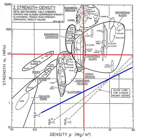
For the material analysis, I also used a separate Ashby plot relating strength to relative cost/unit volume as a cross-reference to determine the optimal material for this application, which ended up being polypropylene.
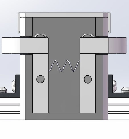
The picture below is an image of the turret mount subsystem I helped design with a teammate on CAD. The turret mount features a compression spring between two pillars with two thumb screws fastened into them. The user pinches the thumb screws, positions the mount into the fixture, then releases to initiate two arms that extend out to hold the mount in place within the fixture, which has a bottom face on the inside.

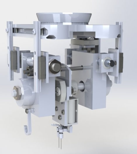
The following picture is our final CAD model after submitting the Preliminary Design Report. In the image, the black part at the top is what the turret fixture would look like on the actual microscope and the turret mount arms would protrude out and interfere with that bottom inner face.

Final Design Report
For our final design report, we were assigned to write an executive summary of our design, explain the design changes implemented based off two design reviews our group had with our professor and TA, create a Kano Model feature evaluation table, perform final system analyses, create a BOM, PO, estimate manufacturing and assembly costs, complete part drawings with tolerance dimensions, submit a final CAD model of the design, and create an assembly manual for our design on our class Pressbooks, which will end up becoming an open educational resource for all engineering students in Capstone Design in the near future. For this report, I contributed to writing the executive summary, explaining all design changes made, creating the Kano Model, assisting in performing a few final design analyses and tolerance calculations, and determining most of the subsystem and full assembly times by using Boothroyd and Dewhurst charts detailing manual handling and insertion times. An image of our final design can be seen at the top of the page, but here are two close-up images of the on-system assembly.

Also, the PDF below is a copy of the executive summary I helped produce, detailing how each subsystem functions and comes together into the final 3D bioprinter seen at the top of this page.
Poster Presentation and Oral Presentation
I've provided images of our poster below. Similar to a poster symposium, we had to present our design, defend it, and showcase how it meets all customer needs. My job was to create the mapping portion seen on the second image below.
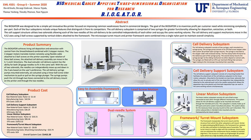

As for the Oral Presentation, the video was posted onto the class YouTube page, which can be seen below.
For more information regarding the Poster and Oral Presentation, all the information and documents can be found on our class landing page by clicking the text below.
SUMMER 2020 – GROUP 6 PRESENTATION
NOTE: Some of the information on the class landing page is incorrect. Refer to Oral Presentation video for the most accurate representation of our design.
Shortcomings & Lessons Learned
During our second design review, we were notified that the turret fixture had set screws and a clamping mechanism to hold in place any part placed within it; therefore, the protruding arms on our turret mount subsystem were unnecessary. This was relieving considering the many complications I came across, especially that of threading into plastic. However, it was also a bit alarming considering we had to create our poster and orally present our final design in a few days before submitting our final design report. However, after doing a bit more research and holding brainstorming sessions with the team, we decided to combine our custom 80/20 nylon framework with our turret mount, which can be seen in our Oral Presentation thumbnail and in the image below.
.jpg)
Our new design ended up working significantly better than the previous one, both functionality-wise and aesthetically. The reason this even happened was because I misunderstood my TA when he was explaining how the turret mount is installed into the fixture. Granted, the part drawings we were provided were incorrect and did not display the clamping mechanisms or set screws; however, I should have verified my TA's explanation with my professor and done more in-depth research on the microscope itself, which would have saved me several hours of stress and time. It ended up working out in the end; however, my biggest lesson was to research well, ensure comprehension, and also coming to peace with the fact that design entails several iterations before coming to a final design.
Results
Each of our reports scored incredibly well with our lowest score being a 94% and our highest being a 104%, far exceeding the class mean each time. We ended up scoring the highest in the class on the Final Design Report (94%) and second highest on the Preliminary Design Report (97.5%). As for our Oral Presentation, we were told that we presented well and received an 80.5% on the presentation. We scored well on each of the rubric's categories, which entailed solving complex problems applying STEM principles, applying sound design to meet needs within realistic constraints, communicating clearly and effectively, conducting experimentation, analysis, & data interpretation, creativity & Innovation, Q&A competence/confidence, and presentation/quality. The many hours our group spent working on the project paid off, resulting in great scores, but more importantly in acquiring valuable skills that promote our growth as future professionals.
Overall Experience & Skills Attained
This project provided me with many opportunities to enhance my technical skills via CAD work and conducting analyses, further promoting my growth as an engineer. However, the most important skills I attained this summer were how to communicate effectively within a group and how to lead group discussions. Despite our communication being limited to voice and video calls due to COVID-19, I learned how to communicate with my group members in a way that promoted project progression, detailing what needed to be done and how we were going to achieve our goals. Each time we received our report requirements I would lead group discussions on how we should approach each requirement, who would be responsible for which requirements, and establish a time frame for everyone to complete those requirements. I set up most of our group meetings via Zoom, set up a Google Drive and Teams folder to stay organized, and took meeting notes to recap what we discussed in case we needed to revisit certain information in the future. In summary, I gained valuable team management skills and a greater appreciation for working in a group setting.
To cap off this project reflection, I wanted to include a Zoom screenshot of my group with our water bottles after submitting our Final Design Report at midnight, which was our last submission for the class. This was honestly the best group experience I've ever had with any project; everyone pulled their weight and worked for countless hours without cutting corners to deliver the B.I.O.G.A.T.O.R. for our senior design project. More importantly though, everyone was kind and supportive of one another throughout the entirety of the project. If anyone needed help, another team member would hop in to help out. We filled in any gaps, encouraged one another, and had no negative arguments or issues throughout the project. This was the best group ever, hands down!
.png)